Trigger Messages Using Bits of a Variable
In the previous step, we looked at using numeric variables and thresholds to trigger messages.
But often you just want to use a simple boolean logic to trigger messages. For example you might want to show a certain message when the PLC sets a certain switch and hide the messages as soon as the PLC resets the switch.Toggling messages like this is a piece of cake when using the bits of a variable.
So in the next step, we'll learn how to trigger messages by toggling bits on a Data Variable.
1. Import Trigger Variables
Next, we need to create a variable that we can use to trigger messages based on certain bits. Fortunately, there's already one we can use. Let's add it to our project.
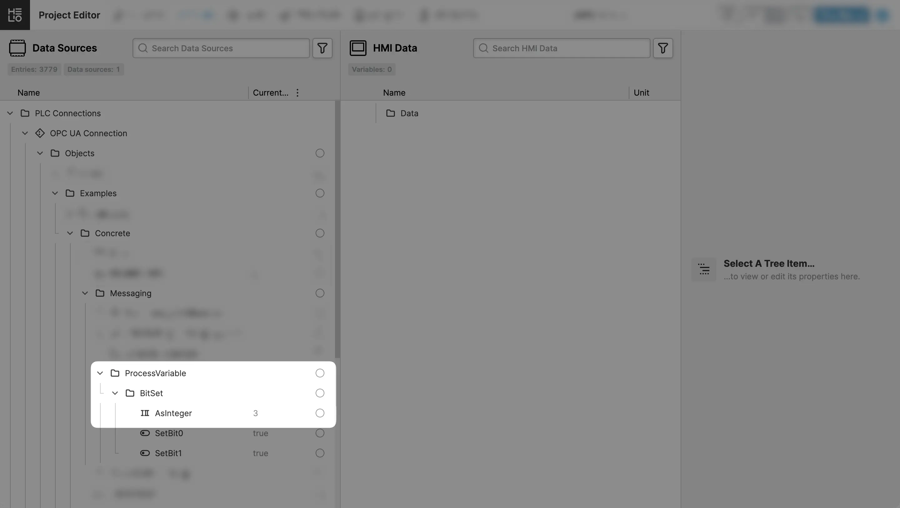
- Locate the
BitSet/AsIntegerVariable
Locate the variable in the Data Source Explorer.
You should spot it under:
Objects > Examples > Concrete > Messaging > ProcessVariable.
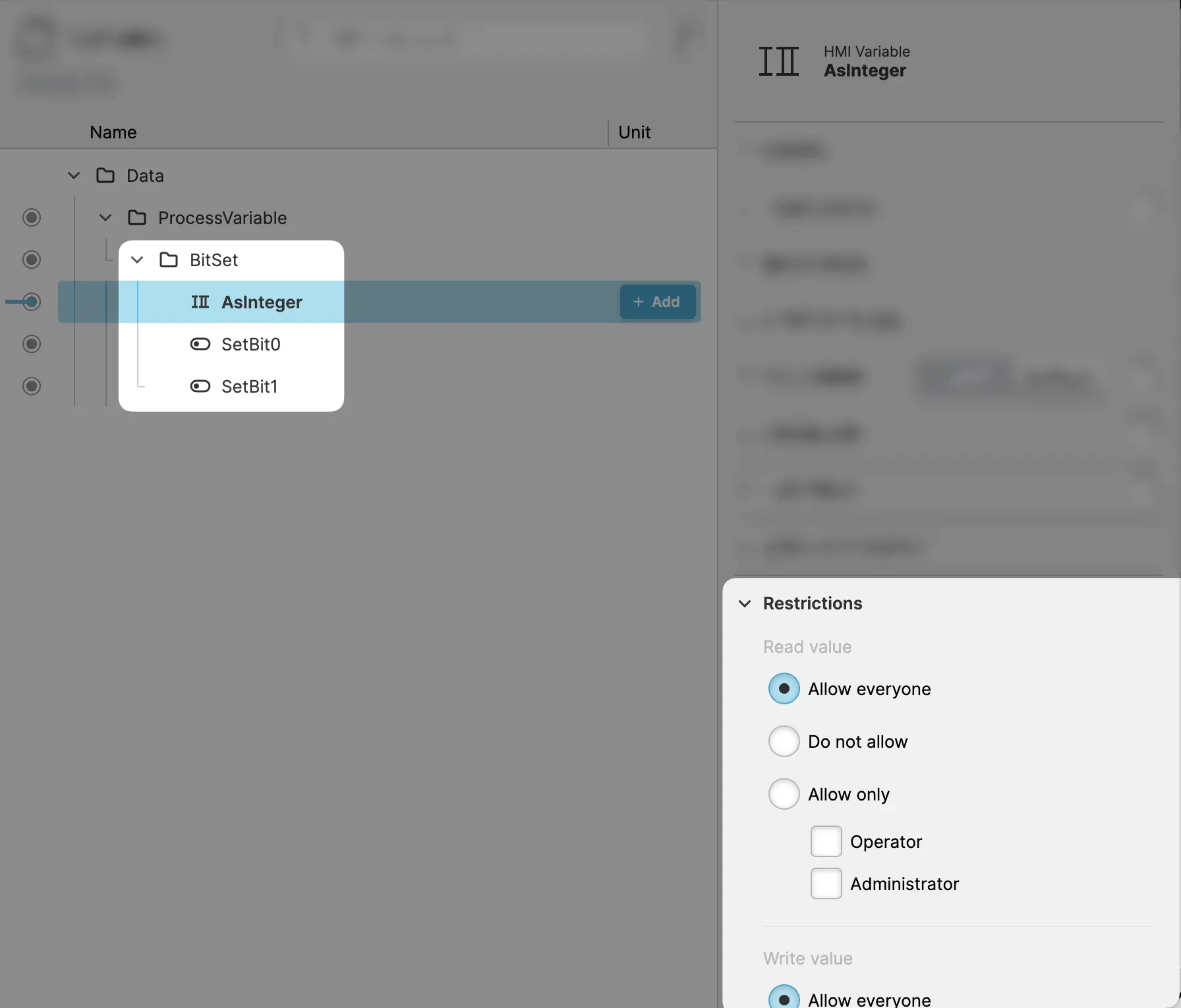
- Import the Variables
Let's import
the variable into your HMI Data so that we can use it in our
project. Since we are also going to use the two additional helper variables
called The two helper variables are needed so that we can set the
bits of our actual Process Variable SetBit0 and SetBit1, simply import the whole ProcessVariable folder.Why Do We Need those Helper Variables?
BitSet/AsInteger. In a real project
this is of course done by the PLC when certain conditions are met.
- Set Restrictions
To be able to write those variables, make sure to loosen the restrictions of the variables, so that we can read and write them.
Your HMI Data Explorer should look something like this:
2. Define Message Types
Now that we've got the source, we need to figure out what the actual message
should be. Let's get started on creating some Message Types.
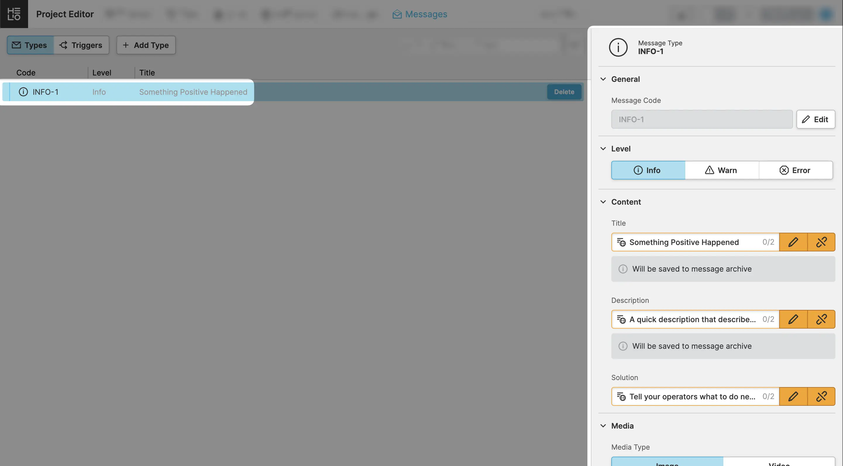
- Add an
InformationMessage
- Switch to the Message Types View view
- Choose the
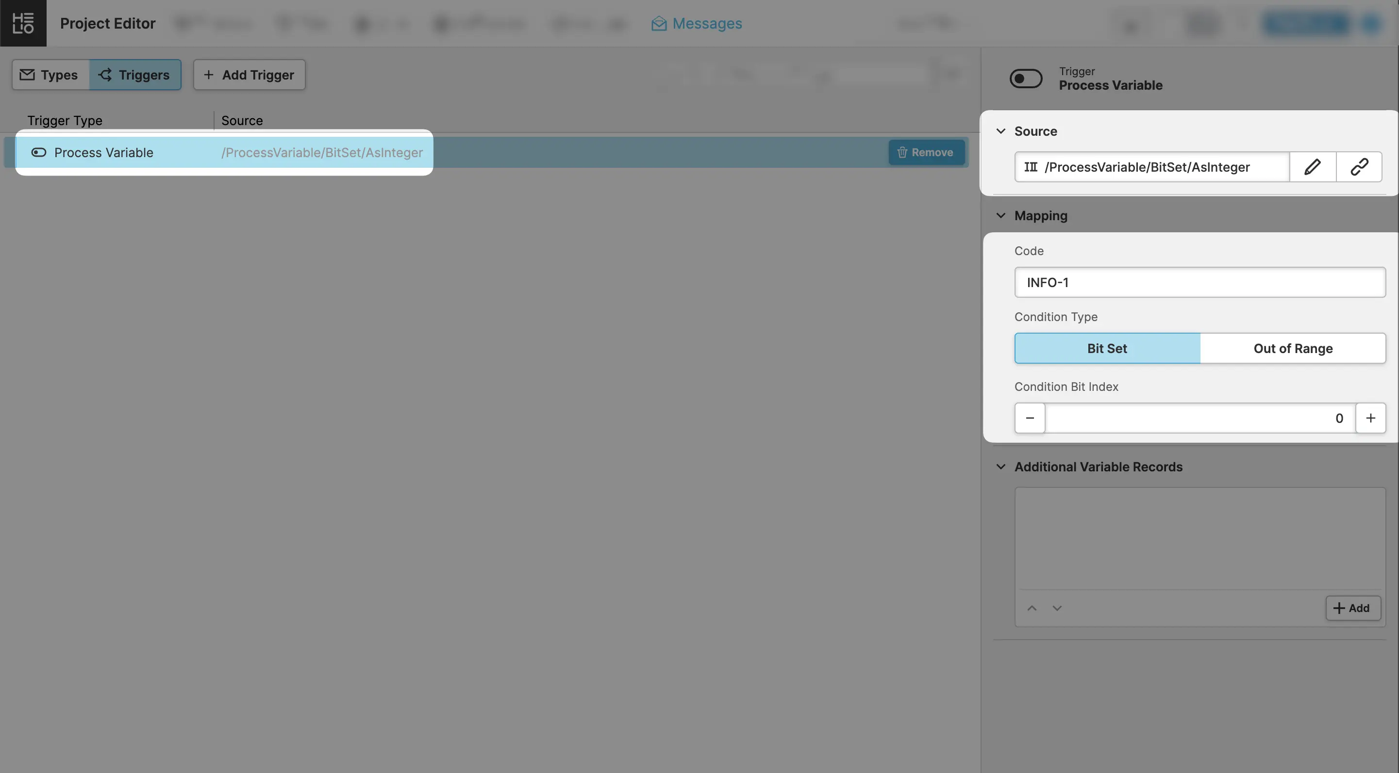
Add Typeaction and enter the details for our first message - The first message we are going to trigger is an Information message, so
let's choose
INFO-1as the code and choose the appropriate level.
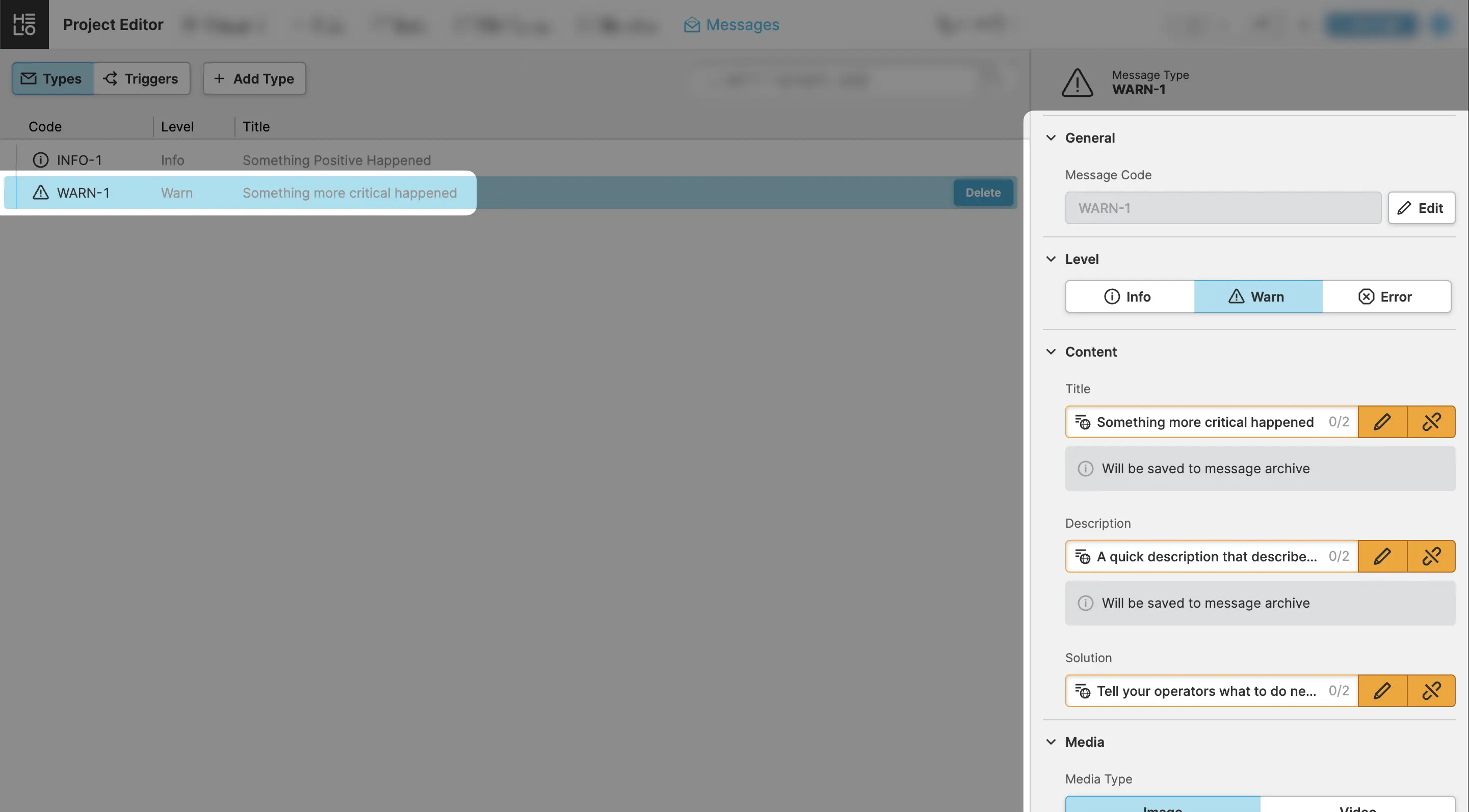
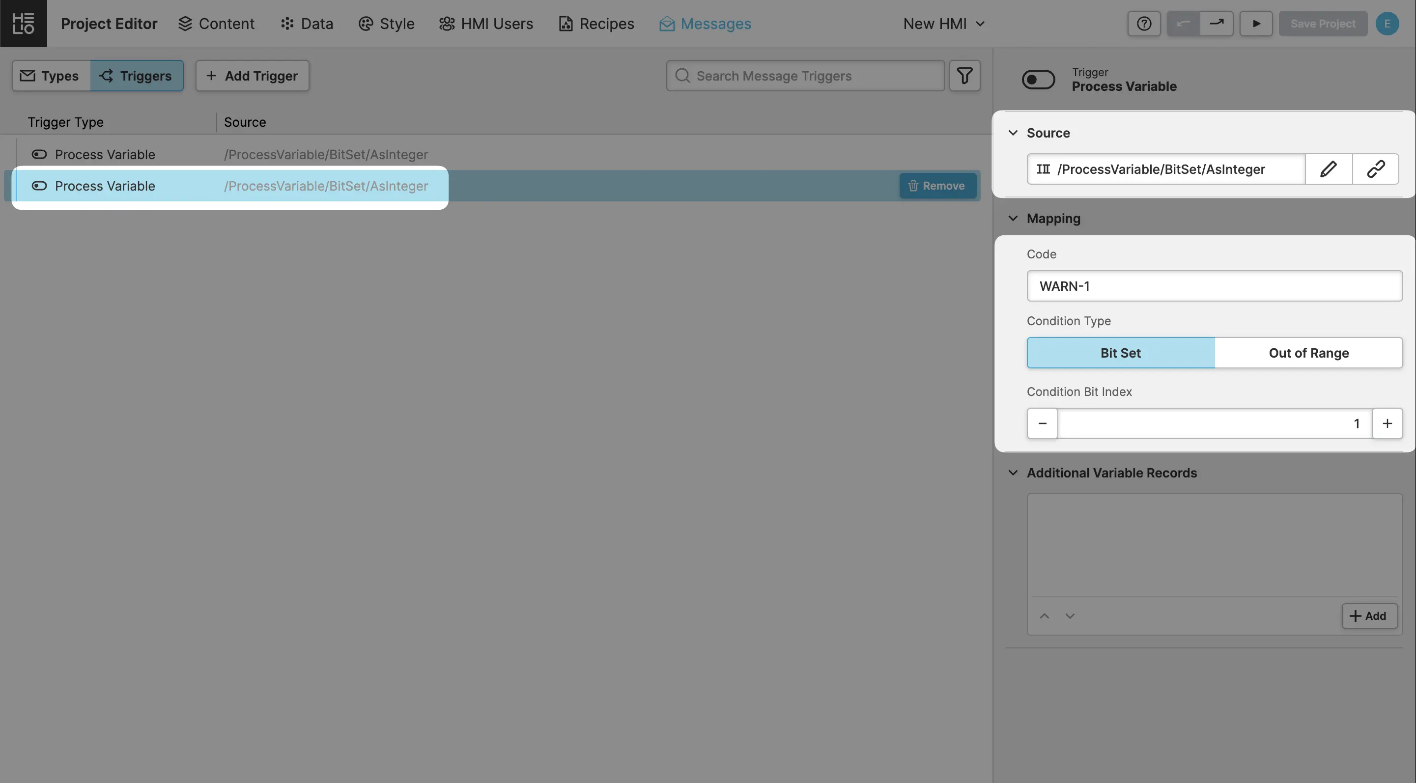
- Add a
WarningMessage
3. Setup the Triggers
Now that we've got a possible source, we need to define an actual Message Type that will get triggered and displayed.
- Add Your First Trigger
Switch to the Message Triggers View view, click
the Add Type action and choose Process Variable as a trigger type.
- Configure the Trigger
Our first trigger is going to show our INFO-1 message whenever the bit
with the 0 index of our variable is set.
- Make sure to choose the right
Sourcevariable. - Enter the
Codethat goes with the message we just talked about. - As the
Condition Bit Indexyou'll want to choose the0here because the condition should be watching the first bit of this variable.
- Add Your Second Trigger
4. Create a Page to Trigger Messages
The excitement is building because we're all set to start sending messages to our HMI. All we need to do is create a small page to simulate the whole thing. Thanks to HELIO, it's pretty simple. So let's get started!
- Add a Page
First things first, we need to create a page. To keep it simple, we're just going to create a basic Parameter Page:
- Switch to the Content View.
- Add a Parameter Page.
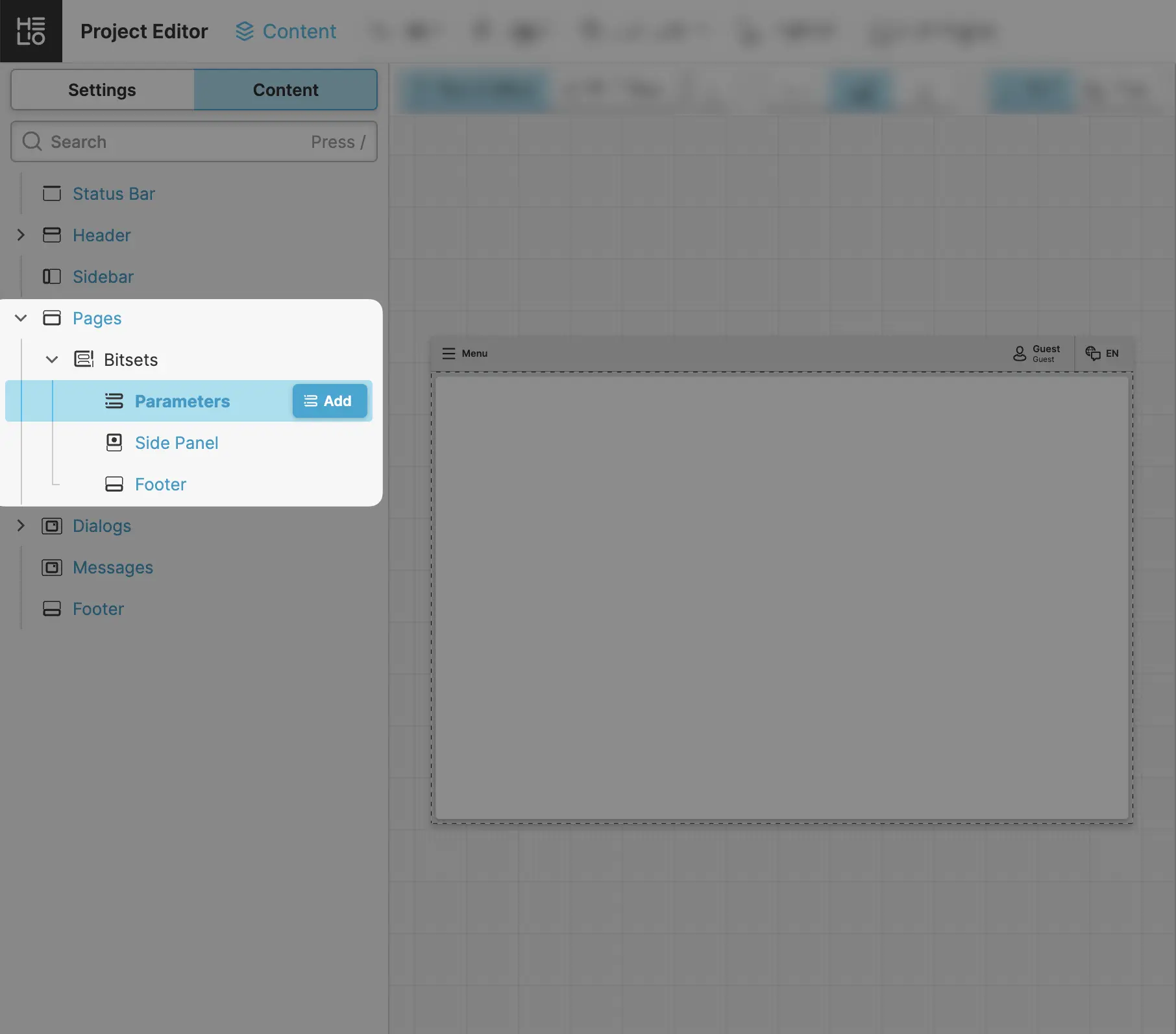
- Add two Magic Inputs and connect them
Next we're gonna need two Magic Input elements so we can toggle our Boolean simulation variables we imported into our HMI in a previous step.
Once one of those variables is enabled, the PLC will set a bit in our
Bitset/AsInteger variable, which will then trigger our message.
- Select the
Parametersslot and add two Magic Input elements - Connect the
Valueproperty of the first one with the/BitSet/SetBit0and the second one with the/ProcessVariable/BitSet/SetBit1variable

5. Let's Simulate Messages
Let's Get Those Messages Fired Up!
- To connect to the actual PLC data, just switch to
PLC Mode. - Switch to
Test Modeso you can toggle the inputs. - Activate each of the two bits by toggling the inputs and you'll see the messages pop up.
Your HMI should behave something like this…
You've created your first message types and triggered them using an actual PLC. Ready to learn more how to display all active and archived messages? Check out the next step of the guide…